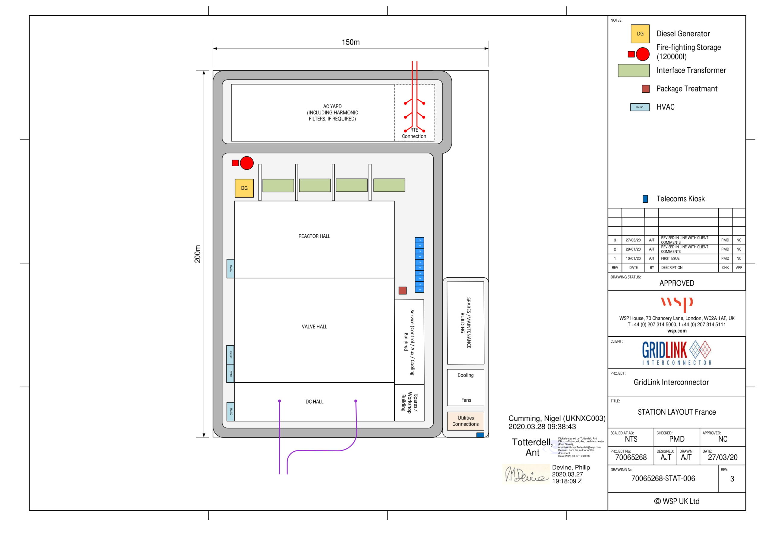
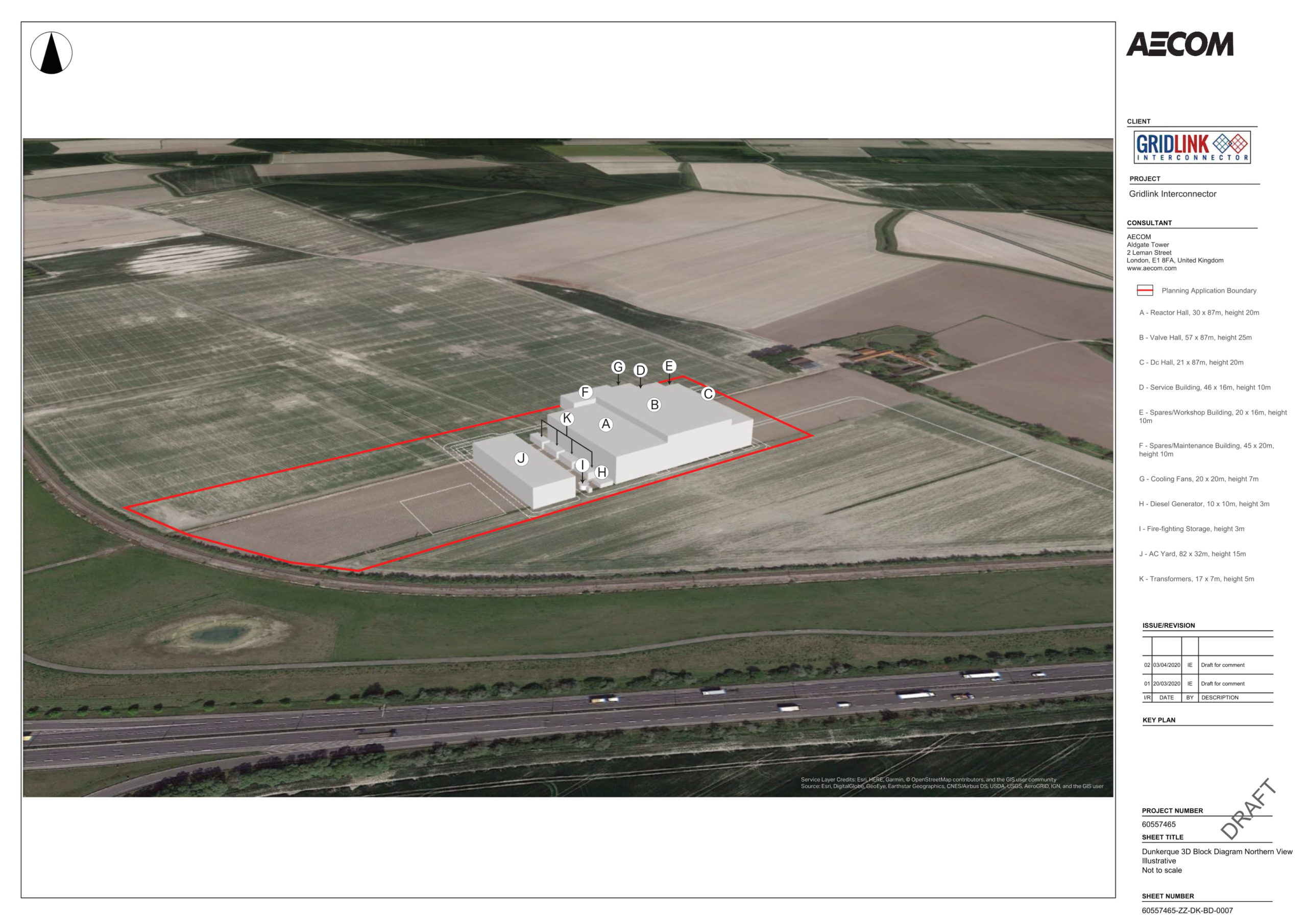
The DC Hall contains the connections to the two HVDC cables that transfer the power between the UK and France.
The Valve Hall is the central section of the main building and contains multiple stacks of power electronics that are central to the conversion process from direct current to alternating current. There will typically be two rows of three stacks of converter modules, with each stack supported approximately 3 m above the floor and with a 3 m gap to the walls, ceiling and other stacks.
The Reactor Hall contains three air cored reactors that are placed on steel structures. The reactors link to the transformers that are sited next to the building.
The Interface Transformers are an interface point between the Reactor Hall and AC Yard. There will be three single phase transformers in use at any one time with a spare transformer located on site in reserve.
The AC Yard will be an outdoor area containing the electrical equipment required to protect the Converter Station in the event of a fault and to enable switching, isolation and earthing for maintenance. The AC Yard will also include the HVAC cable sealing ends of the HVAC cable that will connect the Converter Station to the national grid substation.
The Cooling Fans provide a cooling mechanism for the valves (located in the Valve Hall) which produce heat during the conversion process. The fans cool the valves to maintain a correct operating temperature.
A Diesel Generator set will be provided to serve the Converter Station in the event of loss of either the local transmission network/interconnector or local distribution network. The diesel generator will enable the safe start-up or shutdown of the converter station and running of critical systems if mains electricity supply is not available.
The Control Building will house the Control Room, AC and DC electrical plant, DC converter module cooling plant, Heating, Ventilation and Air Conditioning (‘HVA/C’), batteries, auxiliary power supplies, communication systems and an interface with National Grid.
Other supporting systems and equipment that will be installed at the Converter Station comprise a fibre-optic telecommunications system, surface water/stormwater drainage system and a fire-fighting system, including fire water storage.
Internal site roads will be developed to enable access to all parts of the Converter Station site. Low level street lighting of internal site roads and other areas will be provided for safety and security.
Any unused areas within the Converter Station will be landscaped with lawn grass and/or gravel.
A perimeter fence will enclose the Converter Station which comprises a nominal steel palisade fence (with an inner electrified fence, if required for security) approximately 3.4 m in height.